A production tool on a start-up budget, that had to be able to leave
RK Collective wanted LPM to develop stadium seating made using recycled plastic waste and LPM’s WasticFibre technology. The fabric used for the aesthetics was discarded scarves of Iranian women. The project was called Crafted Liberation. Before I could get started on the manufacturing of the seats, I needed to design and assemble a tool. My first iteration of the tool established the manufacturing process, which consisted of vacuum bagging the scarves onto the chair skeleton. The first tool was rudimentary and not close to being production-ready, so a fair amount of refinement was needed.
Read more
Read less
Crafted Liberation (the client) was still in start-up stages at this point, so their budget was tight. This gave me my first constraint. Another challenge was addressing simplicity and repeatability. The tool had to give consistent results in unskilled hands. It was always assumed the tool would not stay on our site, so it had to move to wherever the project went next and be simple enough to train others to operate.
Break the shape into three, then make the tool its own oven
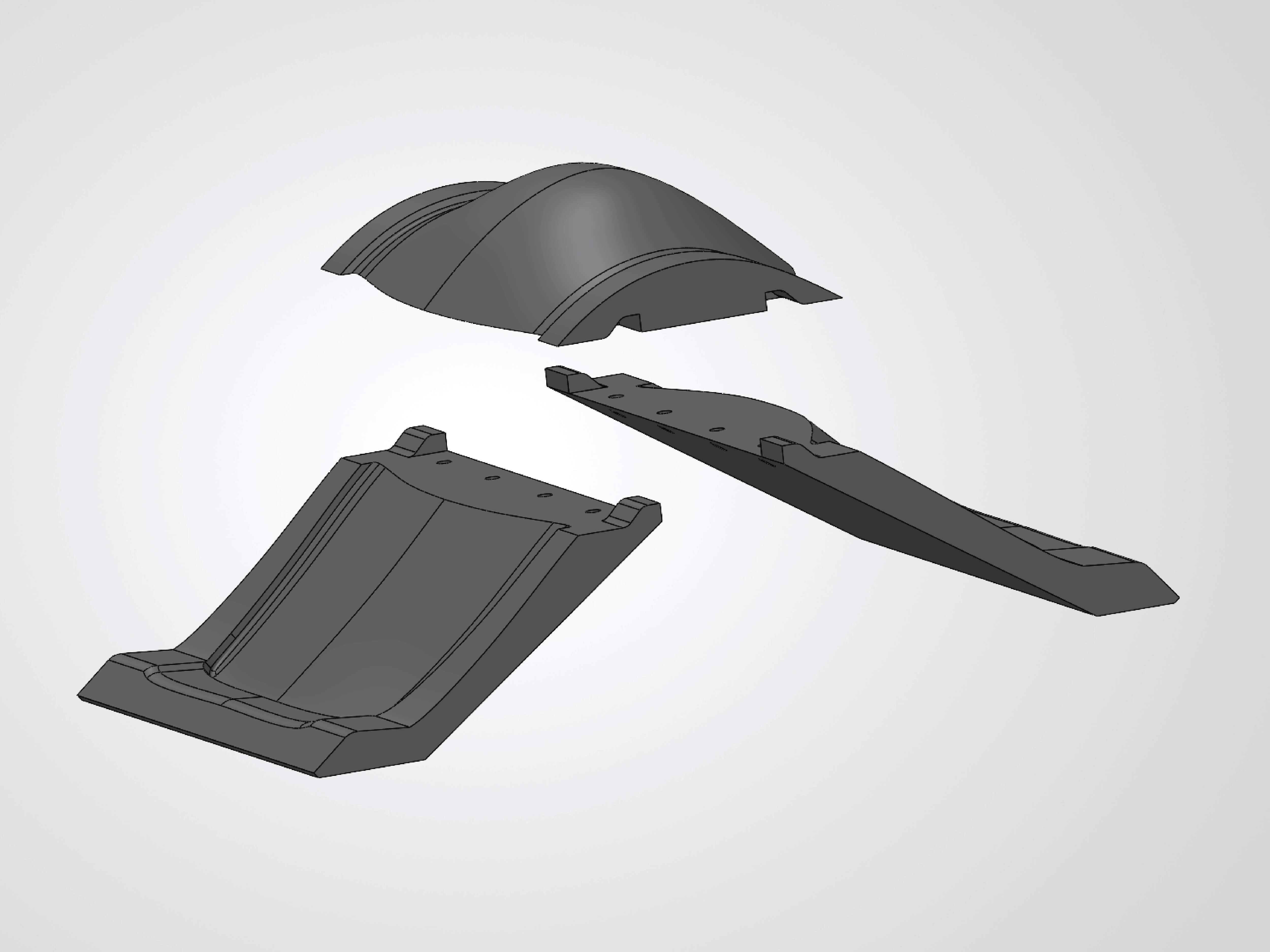
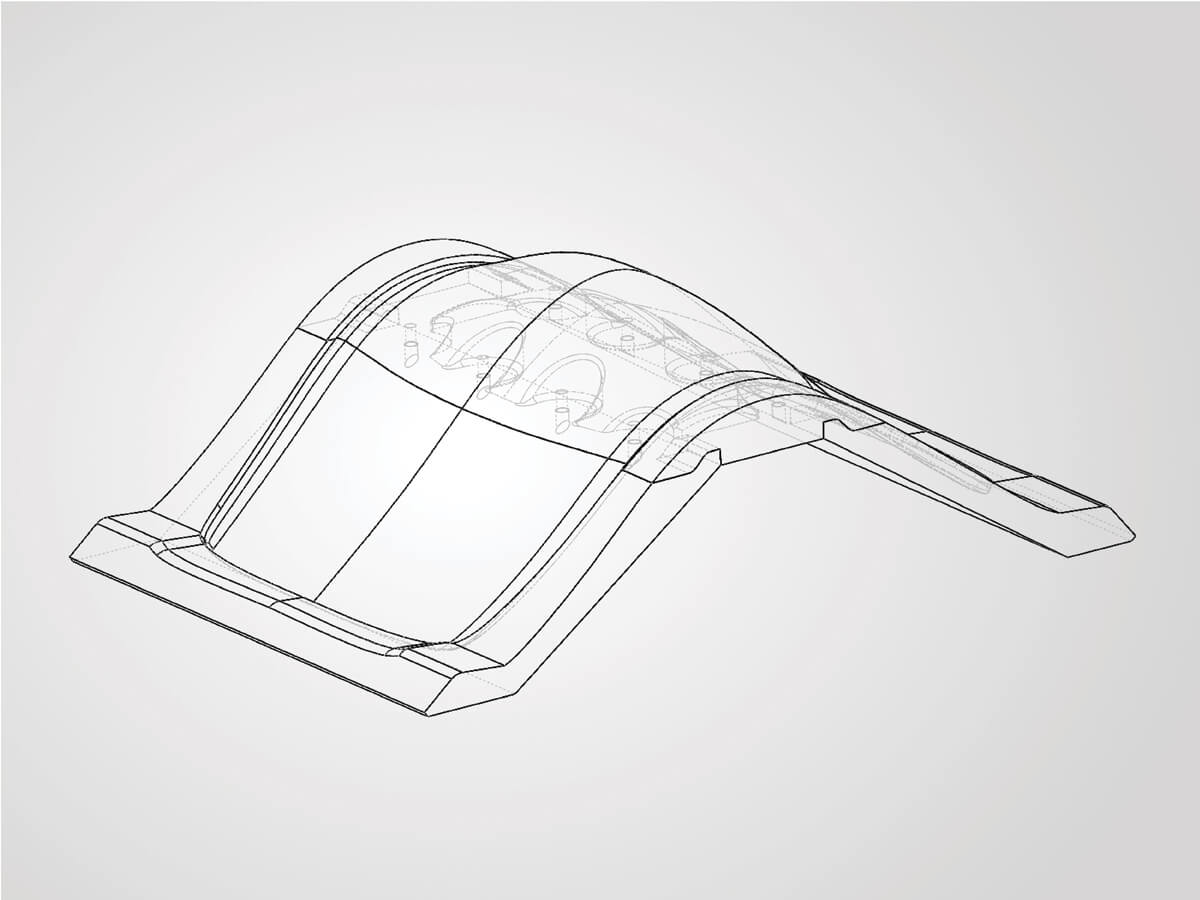
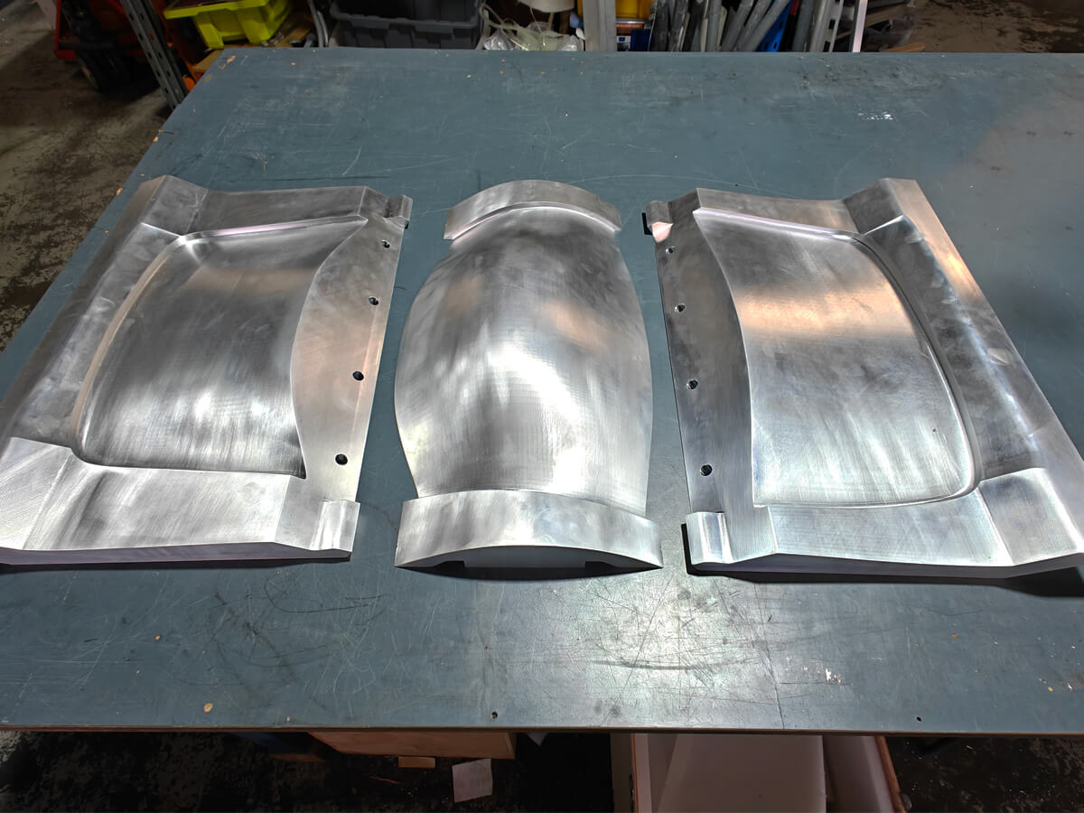
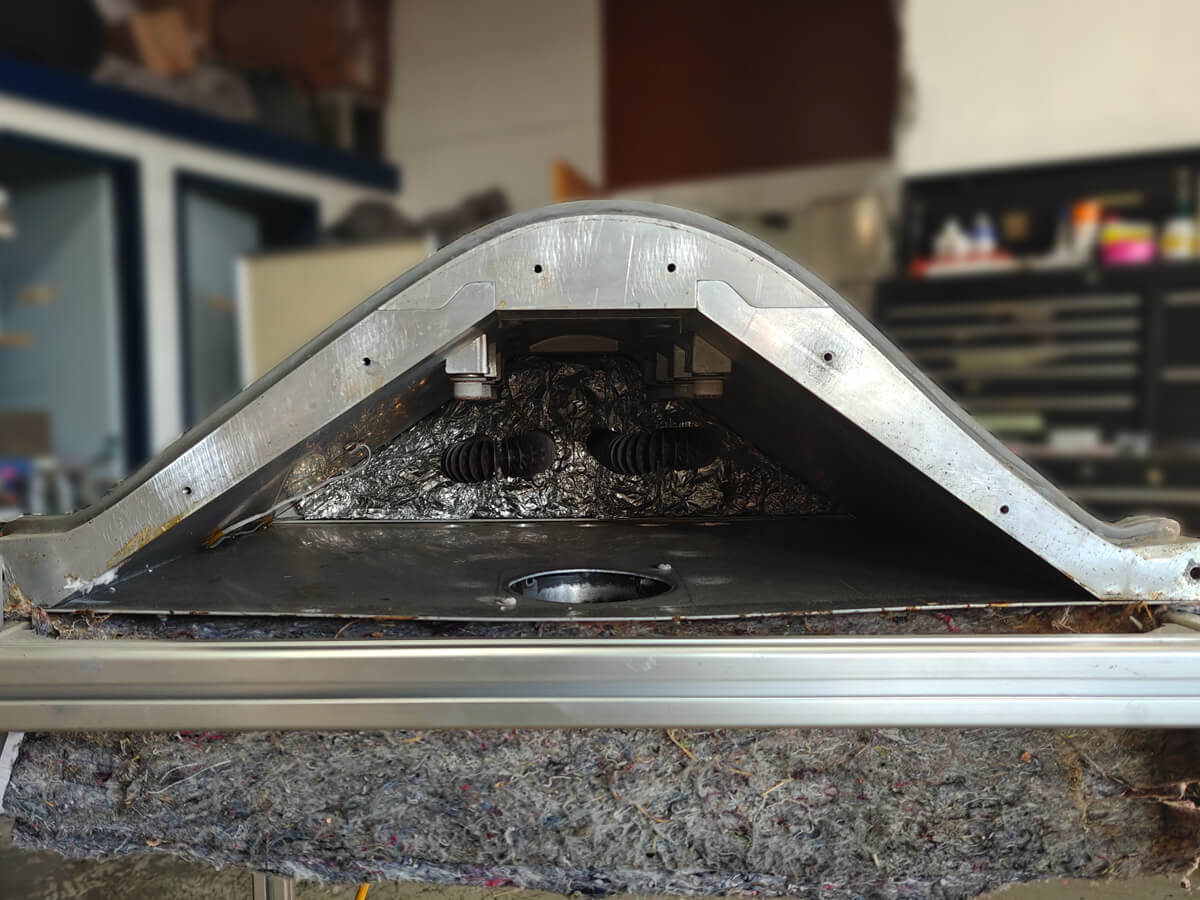
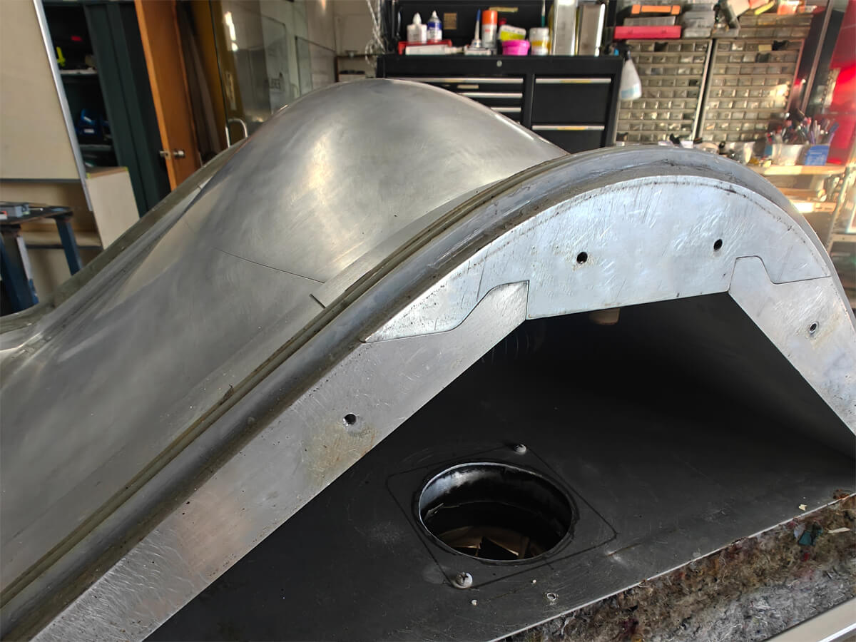
The shape of the seat was provided by the client. My job was to work out how to make the tooling, and to assemble it. A tool with a continuous surface is ideal for plastic products because it eliminates the risk of part-line blemishes. However, for the size and shape of each seat, having a continuous tool meant machining an aluminium billet roughly 300 mm thick which would be about 150 kg of material. The machining and shipping costs alone would have blown the budget. So I broke the design of the chair down into shapes that could each be machined from multiple smaller pieces of material. A three-part tool: the seat, the back, and the butt of the chair that joins the seat and back, assembled into an A-frame. While machining three separate tools made a harder setup job for me, it was worth the savings in weight and material cost. By having three separate sections of the tool, it also made it easier to control the thickness of each piece, which was advantageous. Having a consistent thickness along the tool mattered in production to allow the heat to spread evenly across the tool surface.
Read more
Read less
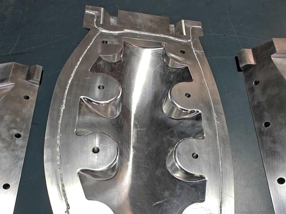
After a couple of iterations and numerous checks, we ordered the tool pieces through a third-party manufacturer. When everything arrived, it all pieced together as designed. I tapped the holes and made some angled blocks to give the bolts a flat seat. The alignment blocks pulled it all into an extremely smooth tooling surface. However, during the first vacuum test I discovered something that we hadn't accounted for. The parting lines between each different section of the tool allowed air to be pulled straight into the vacuum bag. It felt like a big problem at the time and one I had wished I'd realised during tool design. Luckily, with a bit of thought and pulling from previous experiences, the fix was small. I took the tool apart again and etched small channels into the join faces. I was going to seat an O-ring in the join, but decided to fill them with high-temp industrial silicone instead. It would spread the surface better, and because it was a viscous material, would fill the cavity better. The next vacuum test gave me a perfect seal.
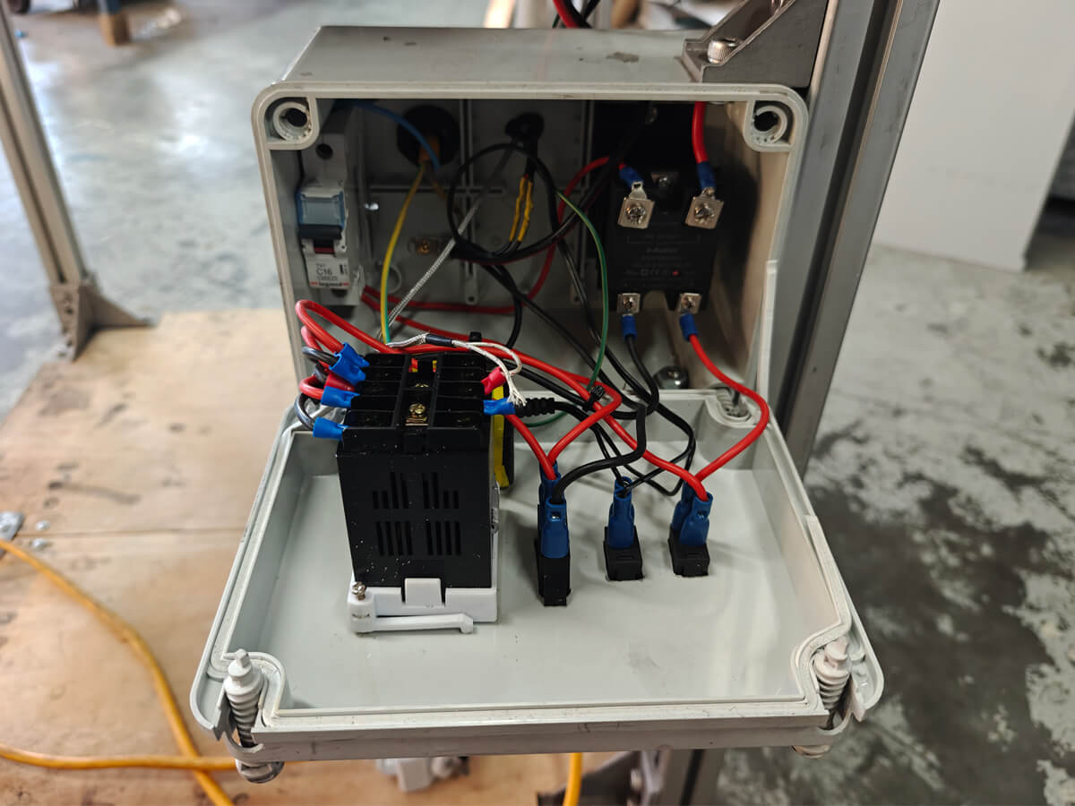
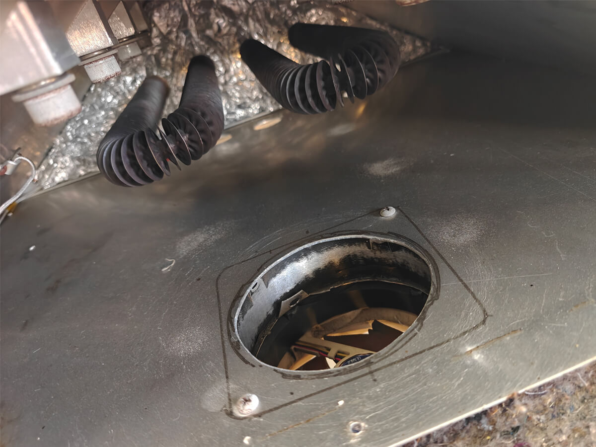
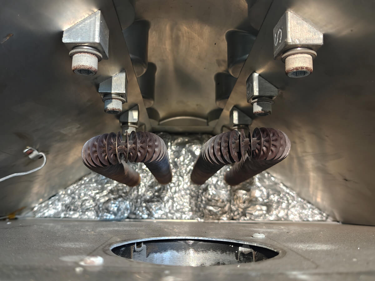
Heating the tool was the next stage of the project. I had always planned to make the tool self-heating, but the approach changed. The original plan was to route channels through the metal to embed heating elements. This is a common approach in the industry but requires an additional machining operation or a lot of manual labour. Instead, I knew there were some spare finned air heating elements salvaged from an old oven in the workshop. These fit perfectly inside the arch formed by the A-frame of the tool, so I built an insulated enclosure around them using the tool as the roof. Using this approach also allowed me to install a cooling system, which was an added bonus. I installed a small PC fan mounted on the floor of the enclosure and cut exhaust holes to push the hot air out. I knew from other plastic work I'd done that the heat cycling of the tool could be the production-rate killer. For the electrical system that ran the heaters, I designed and installed it myself. 240 V for the heating elements and a 12 V transformer for the fan. I rigged the K-probe and the PID controllers to run the heaters and to hold heat in during the cycle. I also stitched a custom-shaped insulation blanket for the tool to ensure an optimised production rate.
Fitting accurately and sealing are two different jobs
This project ran smoother than most, and the vacuum leak was the only real surprise. What it taught me is that designing something to fit accurately and designing it to seal are two different jobs. Anything I design now that has to hold vacuum or pressure gets a sealing plan drawn in from the start, not worked out on the bench afterwards.
Read more
Read less
The budget also showed me that constraints can work in your favour. Splitting the tool into three was forced on me by the cost of a solid billet, but it gave me control over thickness and heat distribution that a one-piece tool would not have.
Twenty-five-plus chairs, and counting
I have delivered twenty-five-plus chairs to date, from prototype development through to finished exhibition pieces. The tool held vacuum and cycled heat reliably across all of them, and it is still in service as the project's production workhorse.
Read more
Read less
Move it in, plug it in and it will make chairs
The chairs have been shown at design exhibitions in Australia, Europe and the US. In 2025, Crafted Liberation won Best of the Best at the Seoul Design Awards, with every chair on show made using my tool. The tool performs exactly as it was designed to on day one: a complete, self-contained manufacturing cell. Plug it in, and it makes chairs. No oven, no fixed infrastructure, nothing it cannot take with it when the project moves to its final scaled facility.
Read more
Read less