Two tolerances on one part, and a launch date set
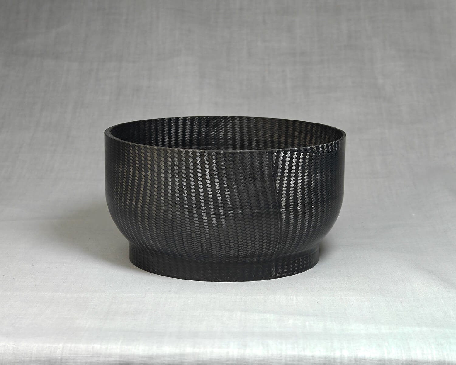
Sunburnt Space Co needed twelve carbon fibre domes for a small-scale rocket fuel tank assembly. The fuel is pressurised, so the parts had to perform structurally, and each dome had to mate with other custom components. That set two critical tolerances: ±0.1 mm on the external diameter at the base, ±0.5 mm on the internal diameter at the top.
Read more
Read less
Sunburnt is a young company with strict budgets, so cost mattered. Timeframes were also tight as they needed the parts ready for the rocket’s first launch around three months after our initial scoping conversation. This all boiled down to needing tight tolerances, real structural loads, completed for minimal cost and as quickly as possible.
Control two tolerances inside and out of the part
Using aluminium for the tooling was the first decision. It is a known and common practice for my work for many reasons that fit our clients' needs. For twelve parts, it keeps cost down without giving up accuracy. I also had a reliable CNC machine part supplier that provides tools quickly and cheaply.
Read more
Read less
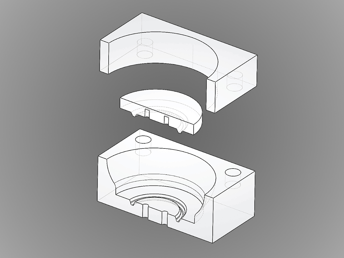
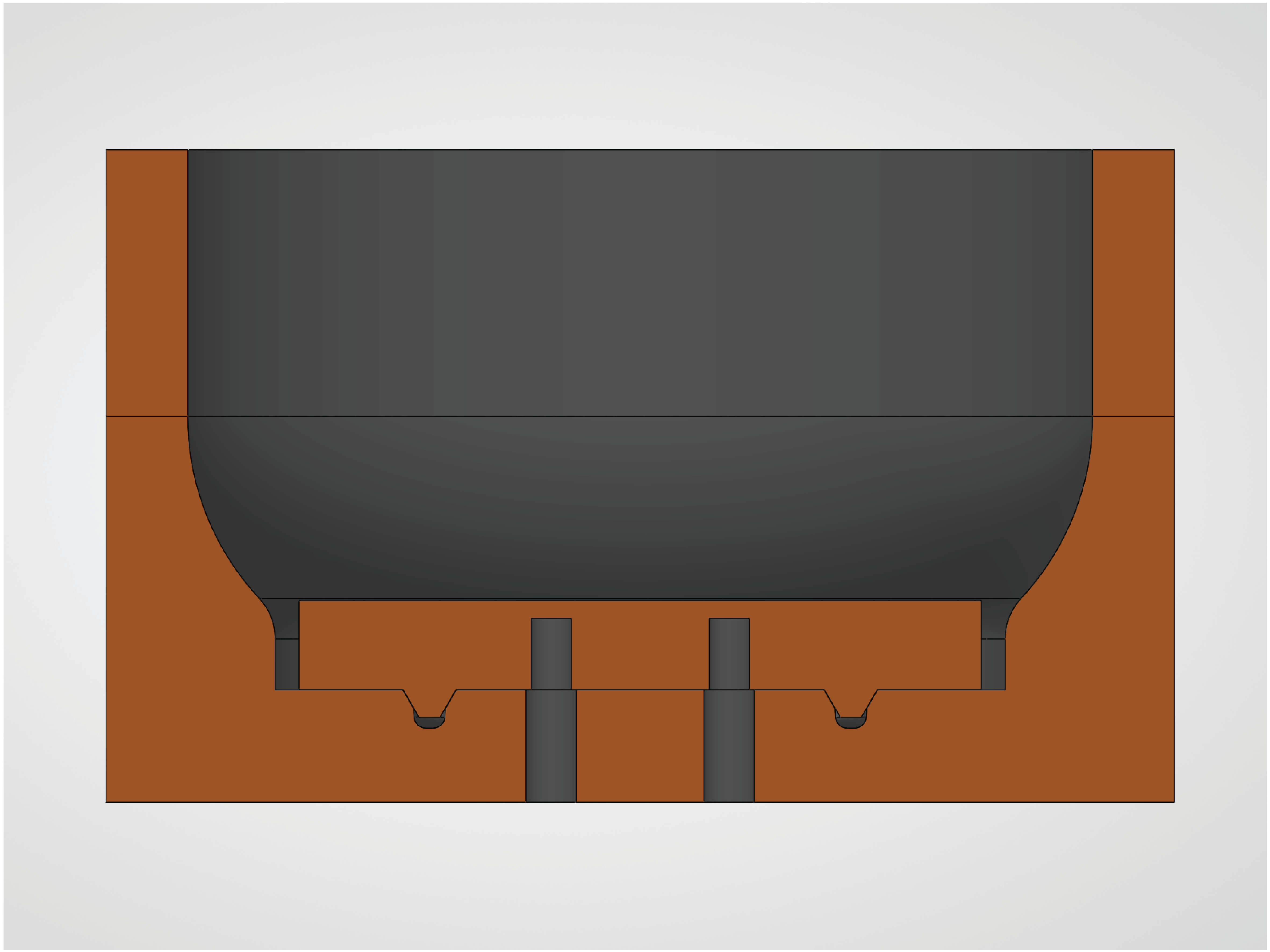
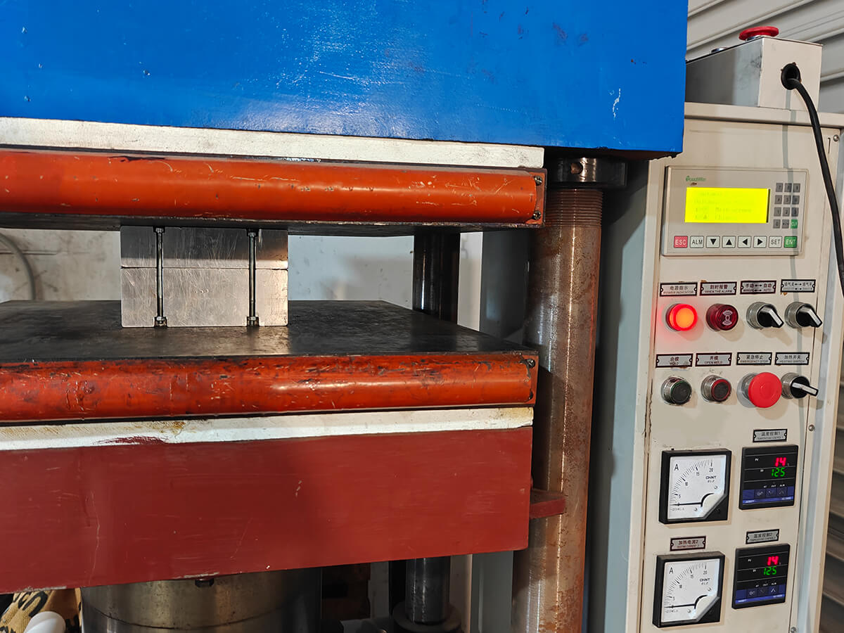
The tool design was harder, because the part carries both an internal and an external tolerance. A male tool was out quickly because the external tolerance was the tighter of the two, and with no tapers allowed due to the need for assembly, detooling would have been a fight. That left a female tool. I considered splitting it vertically down the dome's axis to make detooling simple, but the plan was to cure the carbon using trapped rubber in a heated platen press, and that much pressure across a vertical split risks the halves of the tool moving and blowing the external tolerance. So the tool got a horizontal split through the mid section. I knew that would give me some detooling issues, but previous experience said we could get the part out. The two halves were located by steel push-in alignment pins set into CNC-machined cavities in the aluminium. I installed these in-house.
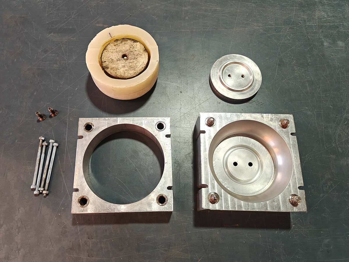
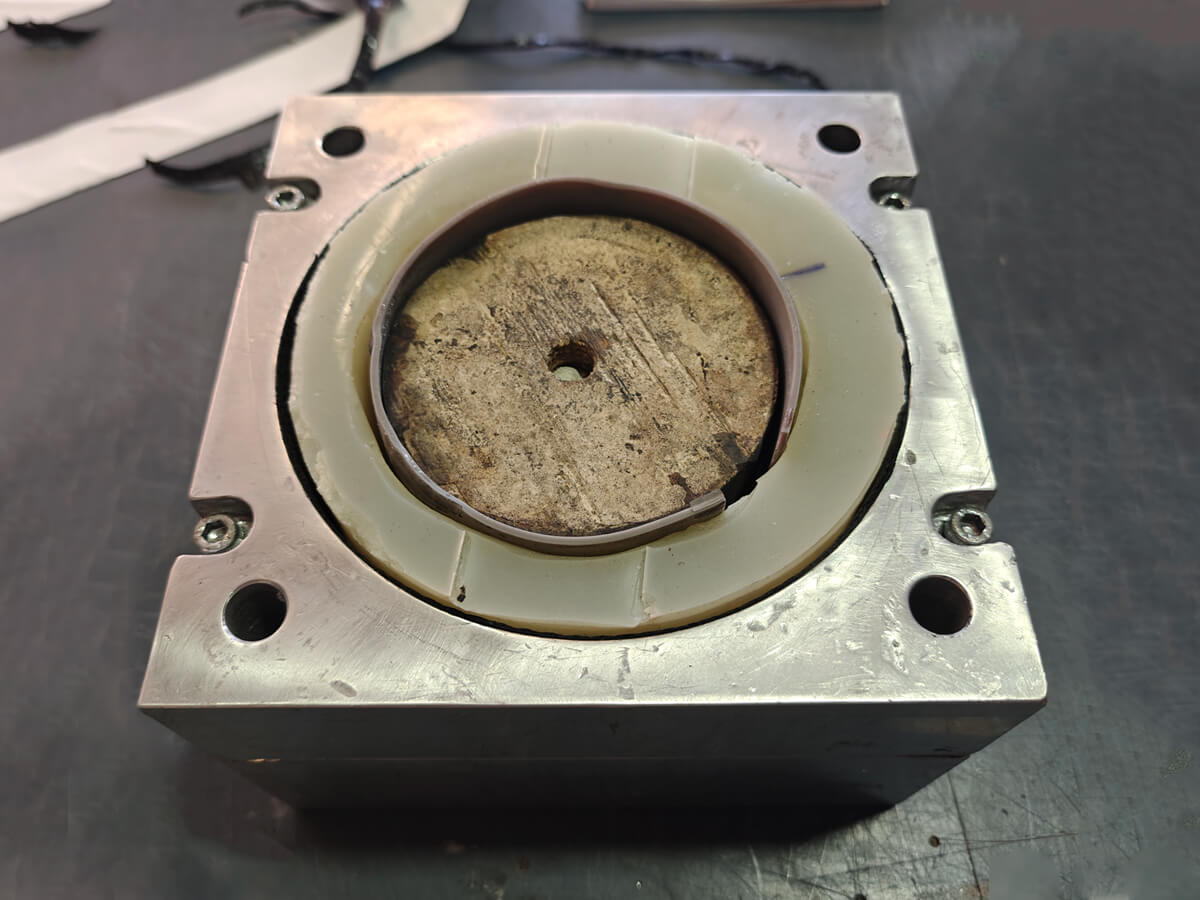
Once the tool arrived, I needed to cast a silicone profile of it for the trapped rubber process. The wonderful thing about trapped rubber is the pressure you get as the silicone expands inside the constrained aluminium tool. The problem is balance: too much silicone, and it destroys itself under its own pressure. I used wax sheets to space the silicone off the tool surface, leaving room for the carbon to fit. I also mounted a wooden block on a piece of acrylic in the centre of the tool so that the silicone would release from the part more easily at detooling. For an idea of the pressures involved: the wooden block in the photos is the same one used to cast the cavity. It is incredible the pressure you get; the wooden block got really squished.
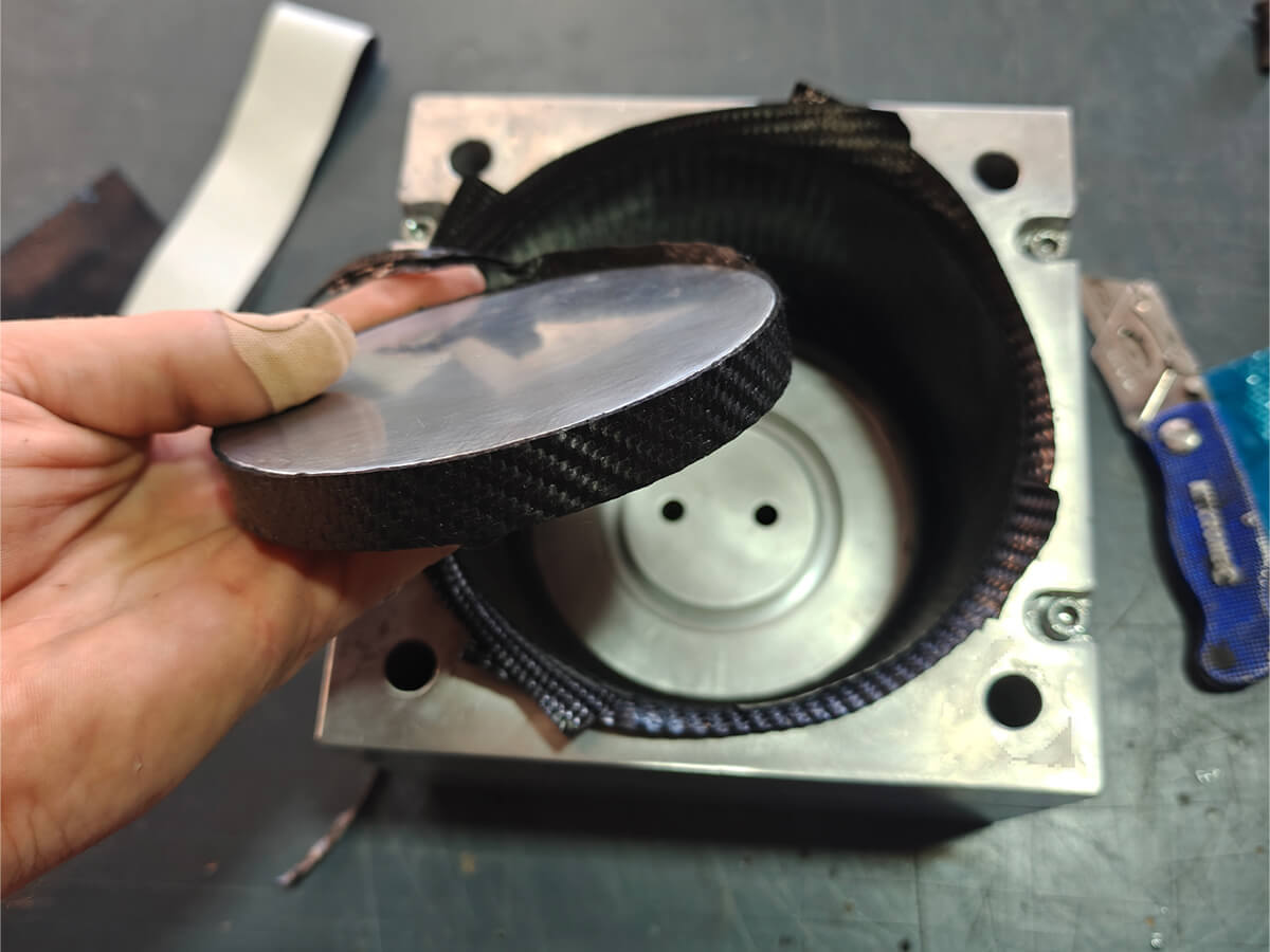
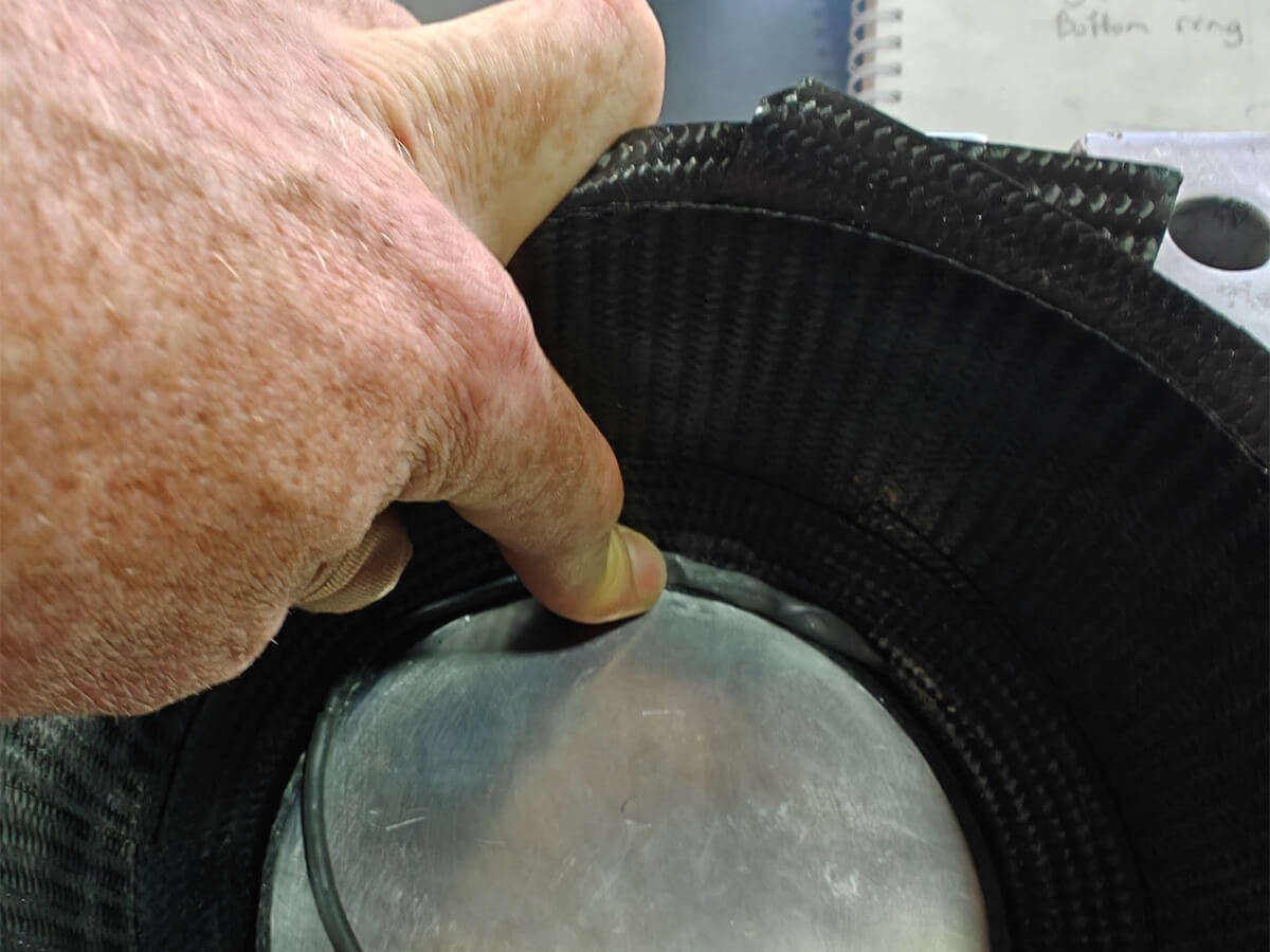
The internal tolerance at the neck of the dome was the biggest design problem. Because I had gone for a female tool, I had no way of controlling that surface yet. The solution was an aluminium puck sitting in the bottom of the tool, holding a 4 mm cavity between its edge and the tool wall. A chamfered alignment channel keeps the puck centred, with a resin channel for squeeze-out below, and two bolts hold it down. At detooling, the puck unscrews and comes out with the part, then gets knocked free with a wooden push jig. It worked a treat.
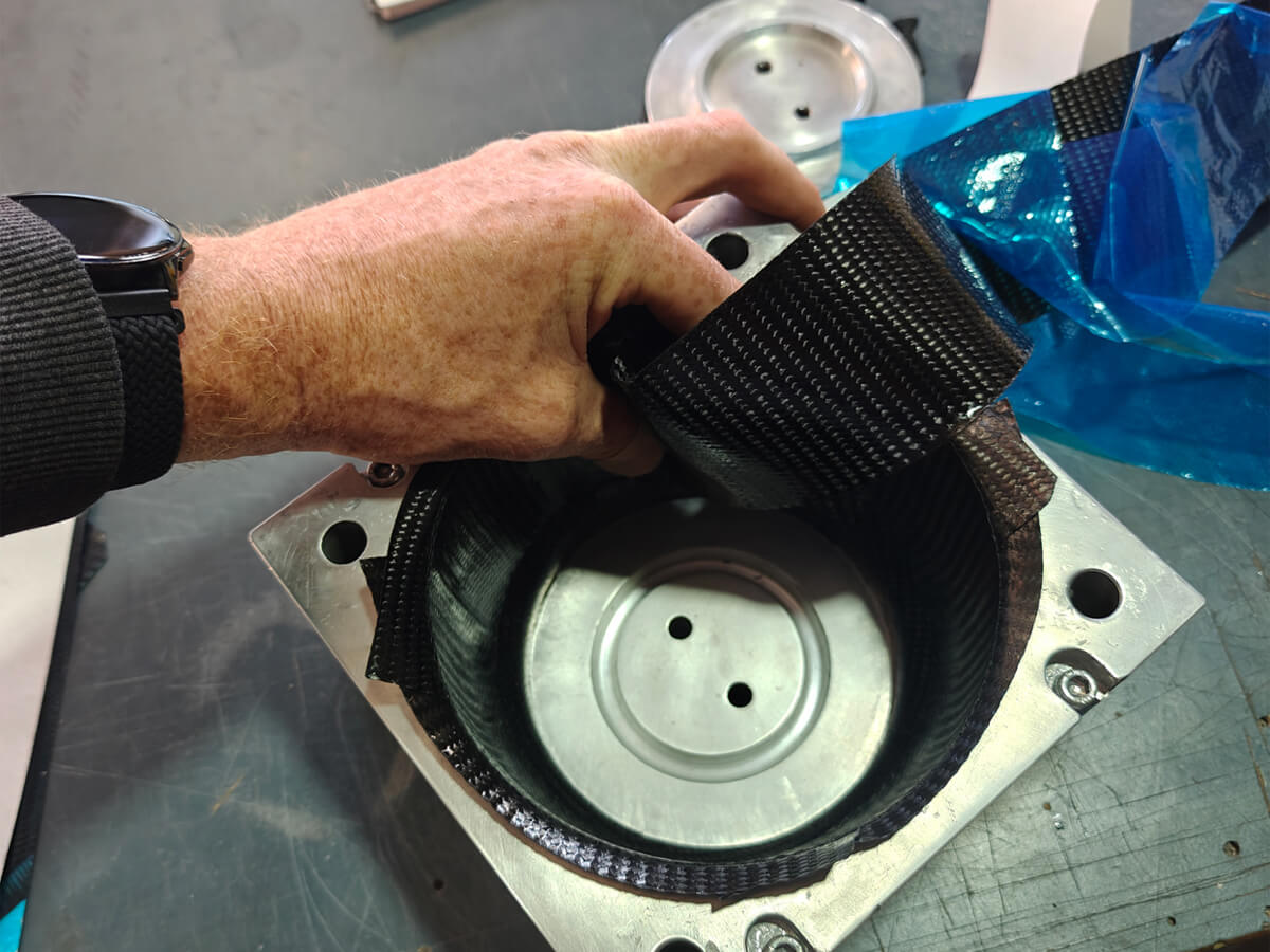
The 4 mm cavity sounds big when we are talking carbon fibre, but this was deliberately generous. We needed to get material into the channel without the carbon bunching or slipping. Strips of woven carbon fibre, cut at 0°/90°, were wrapped around the puck before installation. I also added strips on the opposing tool face. The puck was installed carefully so that a small void remained between the final layers. That void was filled with a prepreg putty, packed in with a slight overfill and some scrap carbon ribbons, so when the trapped rubber expanded under heat, the liquefied epoxy was driven under pressure into any remaining gaps.
For the rest of the laminate schedule, I used 200 gsm plain weave prepreg carbon fibre. The dome's curvature and circumference made the woven carbon tricky to lay at 0°/90°, because the carbon bridges on the curves. Cutting the templates on a 45° angle let the weave stretch to the shape while keeping the strength of the fibres.
Specifics always matter
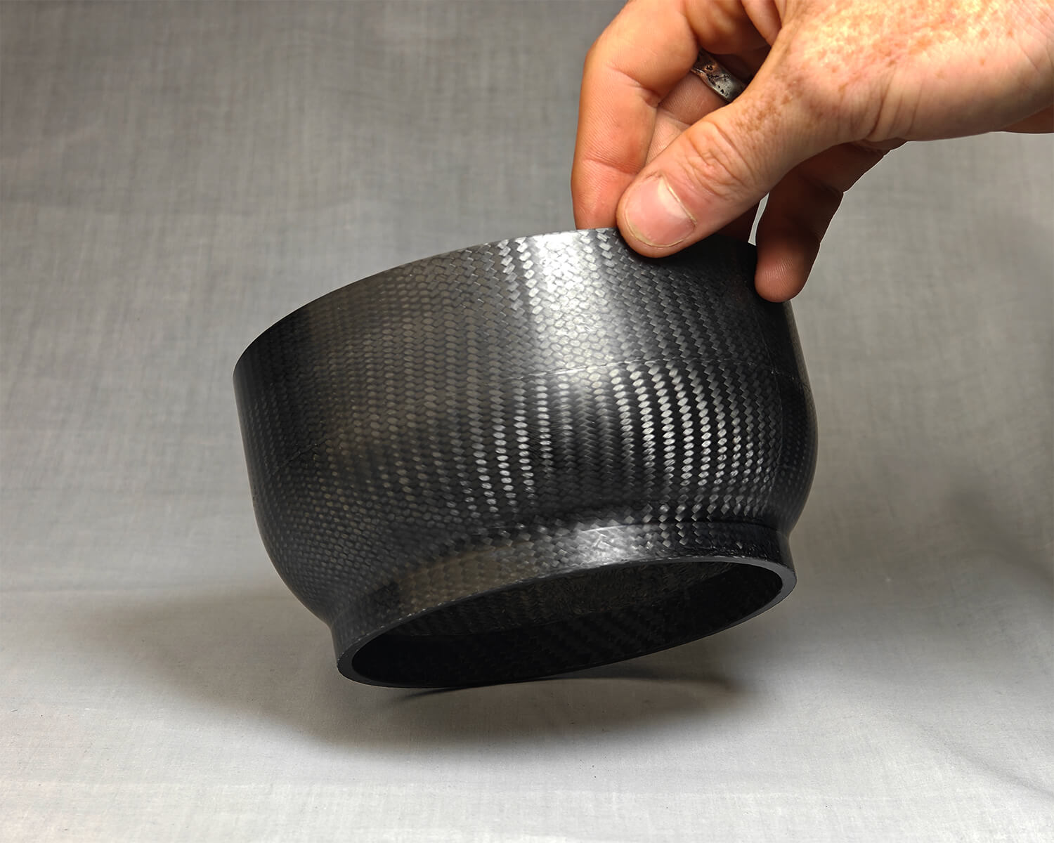
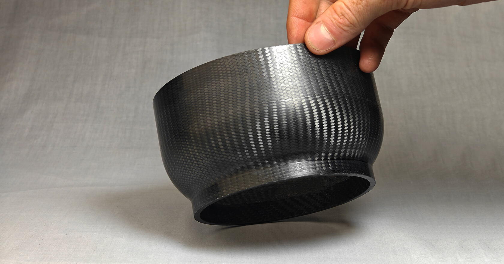
Nothing is ever perfect, and one thing did go wrong. Our tooling supplier deburred and sanded the tool as they normally do, but they also broke the inside part edges, which was not anticipated. I expected half a millimetre of deburr to be invisible in the part, but trapped rubber tends to make these little defects noticeable. The process generates far more pressure than people expect, and it printed that edge into every dome as a pronounced parting line. With the launch date fixed, a replacement tool was slower than labour, so we fixed the defect during the part finishing process. The right call, but a lesson in being very specific with outsourced work.
Read more
Read less
Detooling was an expected wrestle with a taperless part, but I managed to get it done with patience and pre-designed break points. Off the tool, the surface finish was excellent, one of the benefits of trapped rubber pressure, with the parting line the only blemish to address.
Measured against both critical diameters before sign-off
Every dome was measured against both critical diameters, the internal and the external, since the assembly relied on both surfaces mating to adjacent parts. All twelve passed first time. No dome was reworked, no laminate schedule changes, and the tool went the full run without modification.
Read more
Read less
Twelve for twelve delivered on spec and still in use
The twelve domes became six fuel tanks, delivered on budget and in time for the launch. The tanks are still in service as of 2026. The client got a part they could build around, on a timeline a start-up could actually work to.
Read more
Read less