A machine that has to be fixable by the people standing next to it
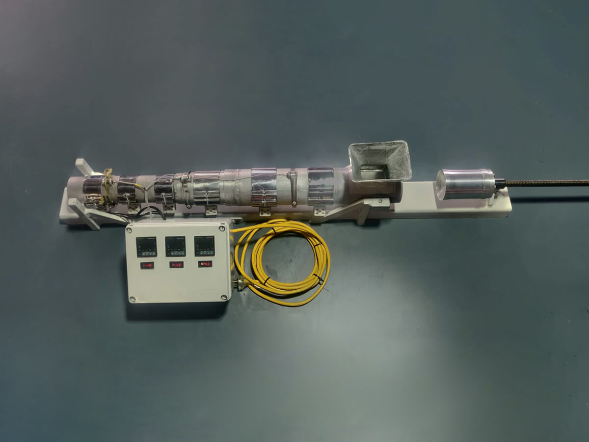
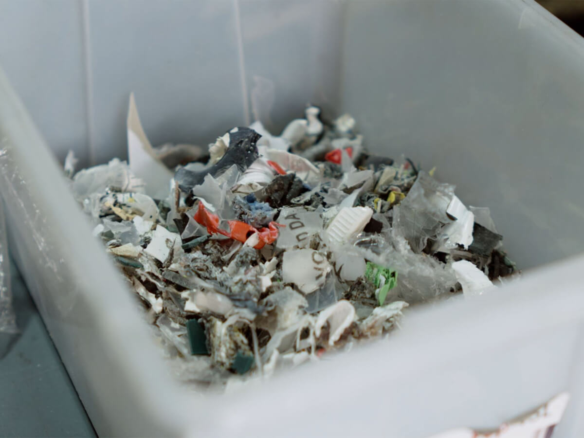
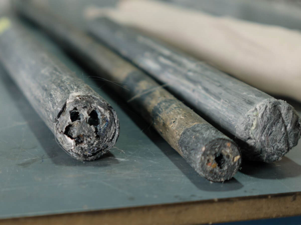
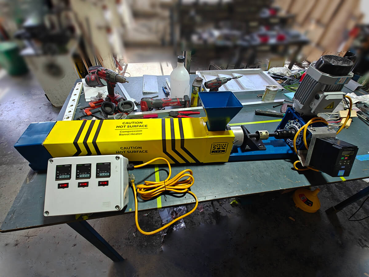
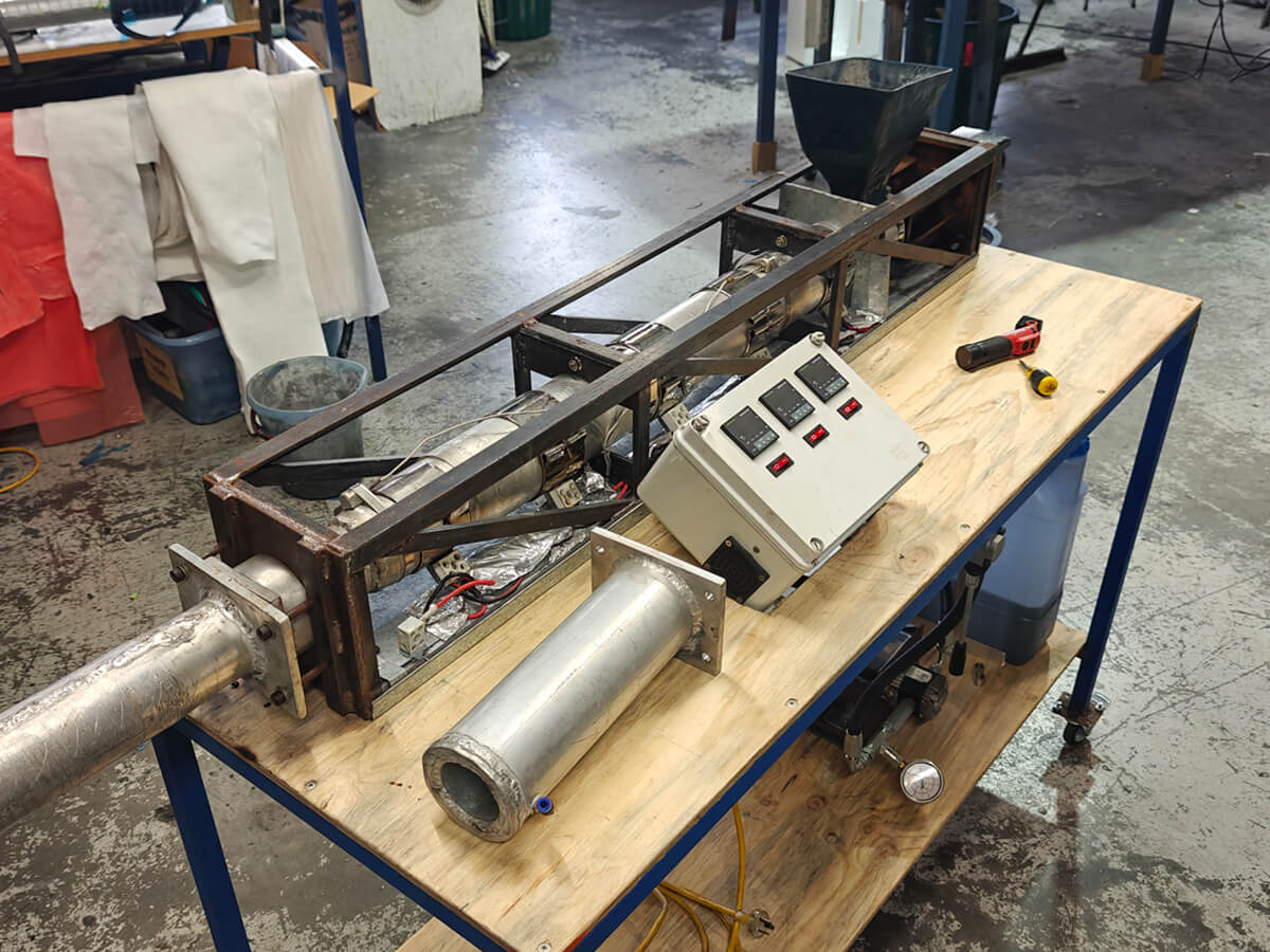
The LPM Compression Barrel Heater (CBH) is an in-house machine for the LPM Project: it consolidates mixed plastic waste and extrudes round profiles, to be used for a street pole product we planned to make at scale. This is the third iteration. I designed and built the previous two versions, so I understood the limitations well.
Read more
Read less
The key limitation to the design of the CBH was the installation location. LPM facilities run in remote places where access to technical parts suppliers is limited. Everything on the machine had to be simple, robust, and repairable. As LPM was still young and developing at the time, budget constraints also favoured a simple approach. Achieving tight tolerances or highly technical performance was not the main priority. Our goal was to engineer a machine that runs consistently and can be fixed by the people standing next to it.
Three generations, driven by two problems: torque and feed
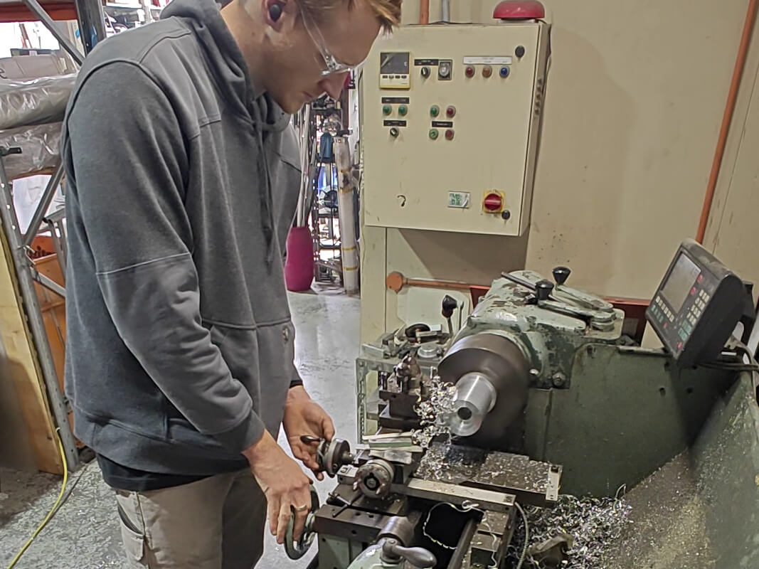
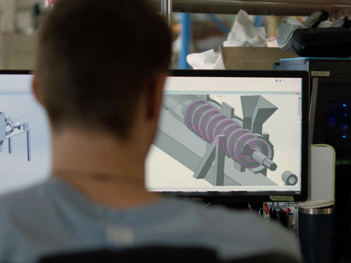
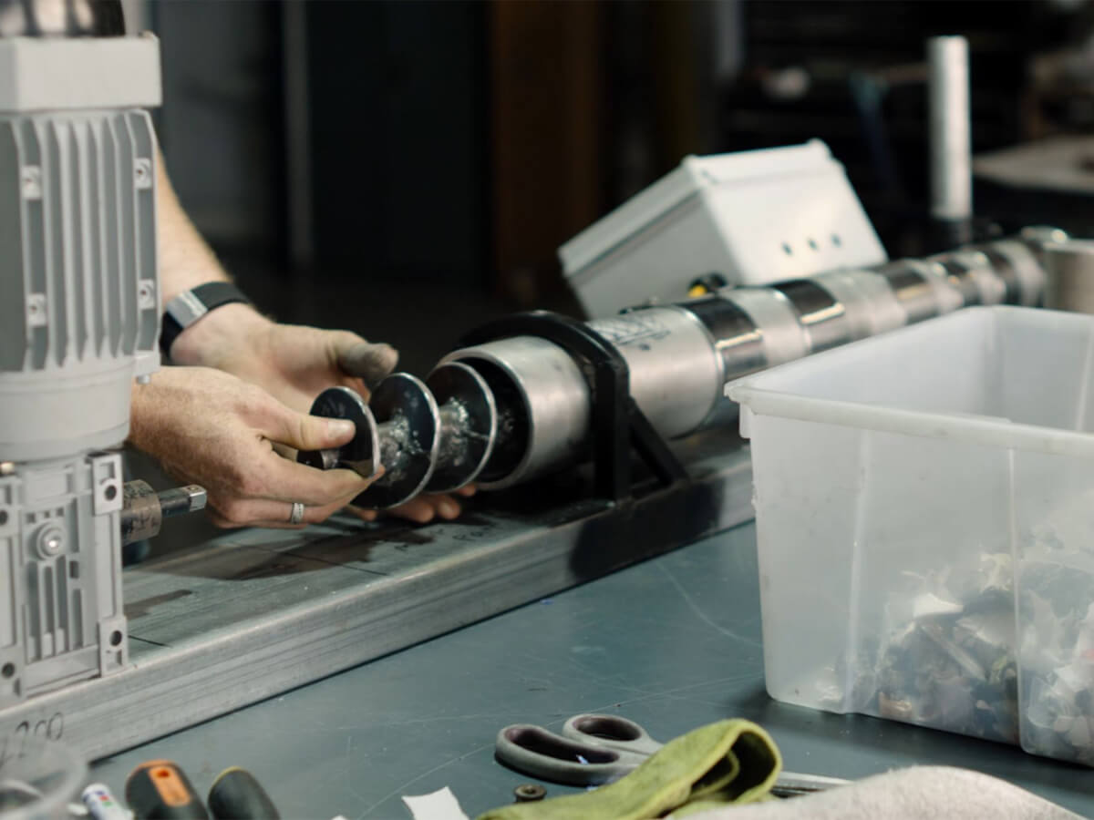
The first iteration of this machine was deliberately basic as we just needed to prove that it could work. Based on experience with similar prototype parts, we adopted a threaded rod-driven piston running on high-tensile Acme threads, driven by hand, to supply pressure to the heated plastic. This turned out to be a terrible idea. It was slow, exhausting, and my shoulder was not happy. After rethinking the approach, I switched to an auger run by an electric motor and worm drive gearbox, a process typically used for injection moulding. Custom augers would have blown the budget, so I found a company to manufacture the flights cheaply and welded them to a steel drive shaft that I machined to fit myself. By version three, the auger had grown longer, with flights that change pitch along its length and a drive shaft running a taper that expands from motor to die head, compressing the plastic as it drives forward.
Read more
Read less
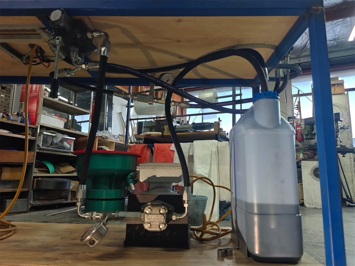
Driving an auger of that size properly to reach the required pressures was the next challenge. The electric motors and gearboxes didn't give enough torque: 150 to 175 Nm after efficiency losses. I expected to need over double that for reliable, continuous extrusion. On a friend's suggestion, I looked at a hydraulic motor and drive system. Research showed potential to not only fix the torque but also cut electrical power draw at the same time, which would be a huge advantage considering the remote install locations. One issue: I'd never built a hydraulic system, and neither had anyone at work. With a mixture of YouTube, AI, and a very helpful sales guy at an online hydraulic parts supplier, I learned enough to design and build a functioning hydraulic power unit and drive. To my surprise, it worked on the first try, tripling our torque output and extruding plastic at an ideal rate.
On the other end of the CBH was a die head to extrude the profile we wanted. This became a very tricky part of the machine, and we have now been through multiple shapes and versions, fine-tuning the extrusion rate. We also needed to design a cooling system as hot plastic coming straight out of a die doesn't hold its shape. The cooling head comprises an aluminium tube and cooling system which has evolved significantly through the development process. What began as a very simple system which relied on spraying water onto the aluminium and blowing a fan over it, became a custom-built shower head and fan system, before we landed on a custom-built, fully enclosed, water-cooled die head. That final version has the profile tube internally, a 10 mm aluminium bar bent in a spiral around the tube and welded in place, and an aluminium tube slid over the top as a casing. Water pumps into the casing at one end, spirals its way around the die head, and comes out the other side. This worked so well. We did originally have the water running in a closed loop, and it did begin to heat up over long runs, but I plan to solve that by running the water through a car radiator.
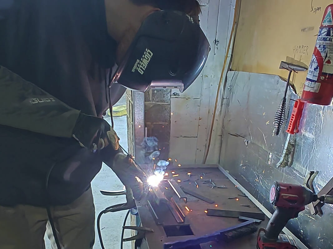
The design of the third CBH version also needed to address structural issues that had become apparent in the initial two versions. Version one generated so much pressure through the screw drive that it flexed the frame. Version two did something similar, even when bolted to a table. I had vastly underestimated the forces and incorrectly balanced the structure, which I was able to rectify in version three. By adding structural supports to the top of the machine and cross-bracing to minimise twisting, I had a frame design I was confident could survive the forces applied to it. I did all of the cutting, welding and fabrication of the frame and the other components in-house. I designed it specifically so that I could remove, repair and upgrade any part of the CBH without rebuilding the machine. It took careful planning, and it worked a treat: I have fully stripped and reassembled this version of the machine three times now.
There is so much more that I have done with this machine than what I have described. Putting four years of development work, fabrication and design decisions on one page would fill a small book. However, there are a few more highlights that I am incredibly proud of:
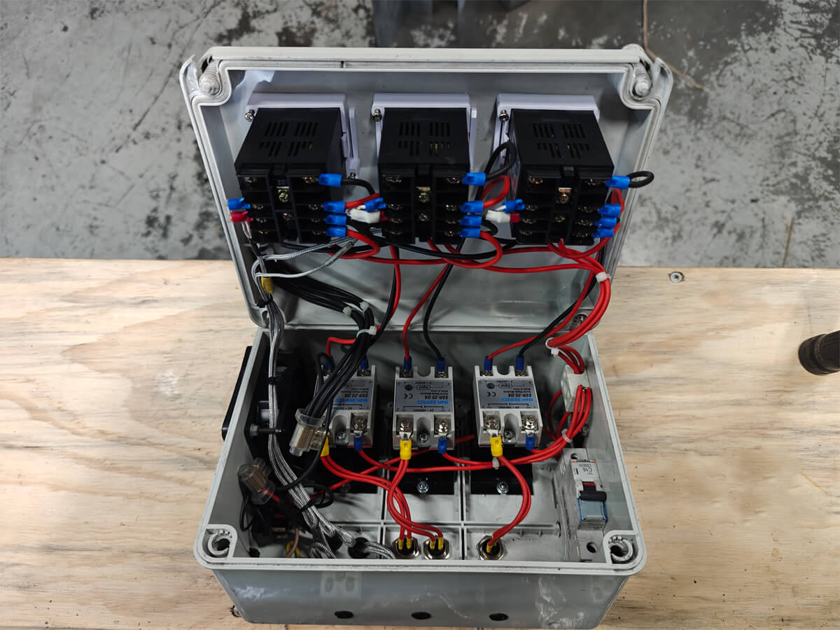
- I designed and built the electrics: the control box, programming the PID control units, installing the heating bands and K-probes, and all grounding and safety requirements, with a couple of electricians looking it over to confirm.
- I manufactured a split muff coupling from a solid steel bar through to an on-machine functioning part. This involved lathe and mill machining of steel, tapping, and accurate cutting for the split.
- I machined and welded the aluminium barrel comprising two stock aluminium tubes (3” and 4”), joined by a custom machined tapered reducer. All parts were completed to extremely tight tolerances. The barrel is the only part of the initial machine that has remained across all three versions.
Understanding the common mistakes is very important
One thing did go wrong with my hydraulic unit: I had to buy a new pump because I made a mistake. I put a lot of thought into the pump and the motor to make sure my auger speeds would be adequate for the process. What I didn't think about was what was happening before them. The hose feeding the pump could not pull oil from the tank easily, so the pump cavitated, and it went downhill from there until it burnt out. Having minimal filtration in the system did not help. I just did not have the experience to understand that this could be a problem in a hydraulic system and looked at it like normal plumbing. It was a lesson that I will not forget.
Read more
Read less
Numerous prototype parts, and a client waiting on the next
I have used the CBH to manufacture numerous prototype parts, and have landed a client who wants to develop a lighting pole using our machine and technology. While still in the prototype stage, the CBH has a very strong foundation and huge potential. With a few final tweaks and optimisations, I believe I can get the LPM CBH running as a fully productionised machine.
Read more
Read less
One machine in Sydney, one that went to Fiji
Of the versions I built, version one was stripped down for parts, and some of those went into version two: the electrical control unit, all of the band heaters, the aluminium barrel and the electric drive motor carried over to version two. The parts that had to be remanufactured were the casing, frame and auger. The second version of the CBH ended up in use in Fiji at our LPM pilot facility, processing mixed plastic waste from the environment into materials used in the production of street poles and cricket stumps. Version three is in use at our Sydney facility, developing prototype parts for our clients. I am constantly learning as I keep using the machinery and thinking of ways it can be optimised.
Read more
Read less